

The 514C controller is intended for use in an Industrial Environment, it should be mounted within an enclosure which provides protection to the controller and the user.
The controller should be permanently earthed at the terminals provided.
The 514C controller is designed to control the speed of a DC Shunt wound or permanent magnet motor. It will provide control of the motor speed in all 4 Quadrants of operation.
The controllers are designed to operate from a single phase AC mains supply in the range of 110 Vac to 415 Vac at 50 or 60 Hz. An auxiliary supply is required for internal power supply generation and main supply contactor sequencing. Coding is derived from the main power terminals and is functional over the whole input voltage range.The Speed of the DC Motor is controlled using a linear closed loop system with a feedback signal from either tachogenerator or armature voltage, the feedback source being switch selectable.A current loop within the speed loop always ensures that controlled levels of current are applied to the motor, actual levels being scaleable via programmable switches.Motor protection is provided by a Stall detection circuit which will remove current from the motor after approximately 60 seconds.Controller protection is provided by an Instantaneous Overcurrent trip circuit overriding control in the event of a Short Circuit.
Technical Specification
AC Supply Voltage Single Phase 110V-480V ;50-60Hz
Current Rating 4A / 8A / 16A / 32A
Overload 150% for 60 seconds
Voltage selection Jumper selection of supply voltage
Speed Control 20:1 (arm v f/b),100:1 (tach fb)
Digital Inputs Run,Enable,Stall override
Digital Outputs Drive health
OPERATING ALTITUDE Up to 1000m ASL
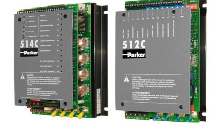
Parker 514C & 512C Part Number:
| Part No. | Current | Part No. | Current | Part No. | Current | ||
| 506/3A | 3A | 512C/8A | 8A | 514C/8A | 8A | ||
| 507/6A | 6A | 512C/16A | 16A | 514C/16A | 16A | ||
| 508/12A | 12A | 512C/32A | 32A | 514C/32A | 32A |
Parker 514C 512C Power Bridge:
514C : 4 Quadrant Regenerative , Dual Three Phase SCR bridges
512C : 2 Quadrant Non-Regenerative , Single SCR bridge
Variable Field Control with SCR’s
Output Current Values:
4A / 8A / 16A / 32A
Typical applications :
- Machine tool spindles
- Wire drawing machines
- Winders/Reelers
Parker 514C 512C Installation Procedure
INSTALLATION PRECAUTIONS
Before connecting AC supplies to this equipment:
1) Ensure good airflow over the heatsink. Maintain clearance of 75mm above and below
controller. For safety maintain a clearance of 20mm at the sides of the controller.
2) Operating temperature range does not exceed 0 to +40.
3) Controller is used in a Pollution Degree 2 environment.
4) Avoid vibration.